#RS 232 SERIAL COMMUNICATION PROTOCOL SOFTWARE#
Hence, this is known as software flow control. This type of handshaking uses two ASCII characters for start-stop communication.

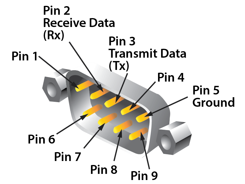
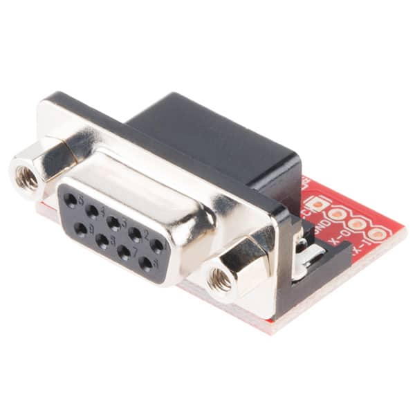
The signals are kept in a high state (logic ‘1’) to activate handshaking. It stops the data being replaced in the receiver buffer. Typically, when establishing communication between a computer and modem RTS and CTS signals are used. It uses control signals DTR, DSR, RTS and CTS signals. The flow control of data transmission and reception is done using hardware handshaking. Handshaking allows the transmitter and receiver device to agree before the communication is going to start. In this case, character ‘C’ is missed by the receiver. If the transmitter sends data at a higher speed, the receiver may fail to receive. While the receive buffer holds the characters received from the transmitter. The transmit buffer holds the characters to be sent to the receiver. In the above diagram, the transmitter and receiver have their own buffer. In null modem cable, the TX (Transmitter) pin of the male connector is linked up with the RX (Receiver) pin of the female and the RX pin of the male is connected to TX pin of the female. To make serial communication possible between DTE and DCE, two types of RS232 cables exist. Other than above signals, (primary signals) RS232 provides secondary signals such as secondary DTE, secondary RTS, secondary DCD, secondary TxD and secondary RxD for optional connection of DTE and DCE. Zero reference voltage level for all the control signals.ĭCE accepts a carrier from a DTE located at remote location.ĭCE is prepared to send and receive the information.ĭetects the incoming ring tone on the telephone line.ĭTE is geared up to receive data coming from DCE.ĭCE is in a ready state to accept data coming from DTE. This signal is connected to chassis ground of metallic connector. Here is a list of signals used in RS232 pinout. Some of them are common ground, Data, control and timing signals. DB9 connector has 9 pins and DB25 connector has 25 pins with each pin having its own function.Īpart from the electrical characteristics, RS232 defined the functions of signals that are used in the serial interface. The D-sub connectors (DB9, DB25) comes with male and female cable. RS232 determines the communication between the DTE and DCE using DB9 and DB25 connectors. Note: The baud rate has to be same at both the transmitter side and receiver side. It determines the speed at which data is to be sent from the transmitter to the receiver. RS232 supports baud rates from 110 to 230400. It is the number of binary bits transferred per second. The advantage of the single-ended technique is, it requires fewer wires to transmit information.
#RS 232 SERIAL COMMUNICATION PROTOCOL DRIVER#
Single-ended signals are affected by the noise induced by differences in ground voltages of the driver and receiver circuits. This means one wire transmits an altering voltage and another wire is connected to ground. The RS232 devices work on single-ended signaling (two wire). The impedance bridging between RS232 driver and the receiver is defined to maximize the voltage transfer between the transmitter and receiver.


Normally, the maximum slew rate allowed is 30V/µsec. The RS232 standard maintains a minimum slew rate with slow rise and fall time to reduce the cross-talk between neighbouring signals. The change of input voltage determines the rate at which the RS232 driver responds. The voltage from -3V to +3V is considered as an indeterminate state. Whereas the control voltage signals use negative logic, i.e., logic ‘1’ indicates -3 to -25 volts and logic ‘0’ indicates +3V to +25V. The signal voltage between +3V to +25V represents logic ‘1’ and the signal voltages between -3V to -25V represents logic ‘0’.


 0 kommentar(er)
